
![]()
2026 Valid JN0-364 test answers & Juniper Exam PDF
Free Juniper JN0-364 Exam Questions and Answer from Training Expert CertkingdomPDF
NEW QUESTION # 35
What is the default route preference for an aggregate route?
- A. 0
- B. 1
- C. 2
- D. 3
Answer: D
Explanation:
In the Junos OS architecture,route preference(often referred to as administrative distance in other vendor platforms) is the primary metric used by the Routing Engine to select the "best" path when multiple protocols provide a route to the same destination. Each routing protocol and route type is assigned a default numeric value; the lower the value, the more preferred the route.
According to Juniper Networks technical documentation, anaggregate routeis assigned a default preference of
130. Aggregate routes are a form of static-like route used to group specific routes into a single, broader prefix to reduce the size of routing tables and limit the scope of routing updates. They are "protocol-independent" because they are not learned from a dynamic neighbor but are manually defined by the administrator.
To understand where130fits in the hierarchy, it is helpful to compare it with other common Junos preferences:
* Directly connected interfaces:0
* Static routes:5
* OSPF Internal:10
* IS-IS Level 1/2:15/18
* Aggregate routes: 130
* OSPF AS External:150
* BGP (Internal and External):170
* Generated routes:150
By setting the aggregate route preference to 130, Junos ensures that specific routes learned via IGPs (like OSPF or IS-IS) are preferred over the aggregate. This is essential because an aggregate route is often used as a
"catch-all" or a discard route when more specific path information is missing. If the aggregate had a lower preference (like 5), it might override dynamic routing information, leading to suboptimal routing or black- holed traffic.
NEW QUESTION # 36
A service provider is onboarding a new enterprise customer that operates multiple branch offices, each with its own set of VLANs. The customer requires transparent Layer 2 connectivity between sites while maintaining separation of internal VLANs. The provider must also ensure that customer VLAN identifiers do not conflict with other customers on the shared infrastructure. Which solution would provide the desired results?
- A. Aggregate customer traffic using GRE tunnels.
- B. Provide Internet access with NAT and firewall services.
- C. Deliver Layer 3 VPN services using MPLS.
- D. Extend customer VLANs using Q-in-Q tunneling.
Answer: D
Explanation:
In a service provider environment,Q-in-Q tunneling(also known as 802.1ad or double-tagging) is the standard solution for transporting multiple customer VLANs over a shared provider backbone while maintaining total separation.
According to Juniper Networks documentation, Q-in-Q works by adding a second 802.1Q tag (theService Provider tagor S-tag) to the customer's already tagged frames (theCustomer tagor C-tag). This creates a
"tunnel" at Layer 2. This solution specifically addresses all the customer's requirements:
* Transparent Layer 2 Connectivity:Because the provider simply encapsulates the customer's frames, the customer's internal BPDU traffic (like Spanning Tree) and VLAN tags are preserved and delivered transparently to the remote site.
* Separation of Internal VLANs:The customer can run their own internal VLAN IDs (1-4094) without the provider needing to know or manage them.
* Conflict Avoidance:Different customers on the same provider infrastructure are assigned unique S- tags. Even if two different customers both use "VLAN 10" internally, they remain isolated because their traffic is encapsulated in different provider S-tags.
Why other options are incorrect:
* Layer 3 VPN (Option B):While MPLS L3VPNs are common, they provide Layer 3 (IP) connectivity, not the "transparent Layer 2" connectivity requested.
* GRE Tunnels (Option C):GRE is a Layer 3 encapsulation and does not natively provide the transparent VLAN bridging required for a multi-site Layer 2 service.
* NAT/Firewall (Option D):These are security and address-translation services for internet access and do not facilitate site-to-site Layer 2 bridging.
NEW QUESTION # 37
You are configuring BGP for IPv6 operations. In this scenario, which two statements are correct? (Choose two.)
- A. The router ID uses a 32-bit identifier value.
- B. The Autonomous System Number (ASN) must be a 64-bit value.
- C. The Autonomous System Number (ASN) can be either a 32-bit or 64-bit value.
- D. The router ID uses a 128-bit identifier value.
Answer: A,C
Explanation:
When implementingMultiprotocol BGP (MP-BGP)for IPv6, several architectural constants remain consistent with the original BGP design, while others have evolved to accommodate larger network scales.
Router ID (Option C):
A critical point in Juniper's Service Provider documentation is that theBGP Router IDremains a32-bit value, even when the protocol is carrying 128-bit IPv6 prefixes. The Router ID is typically represented in dotted- quad notation (e.g., 192.168.1.1). In an IPv6-only environment, a Juniper router cannot automatically derive this ID from an interface address, so it must be manually defined under [edit routing-options]. This 32-bit ID is essential for BGP tie-breaking and loop prevention within the AS.
Autonomous System Number (Option D):
TheAutonomous System Number (ASN)was originally a 16-bit value (0 to 65535). However, to address the exhaustion of available ASNs, the standard was extended to32-bit ASNs(documented in RFC 6793). In Junos OS, you can configure BGP using either the older 16-bit format or the newer 32-bit format (often represented in "asplain" or "asdot" notation). While the question mentions a 64-bit value, there is currently no standard for a 64-bit ASN in BGP; the transition from 16-bit to 32-bit satisfies current global scalability needs. Therefore, Option D is the most accurate within the context of current networking standards, as it acknowledges the coexistence of different ASN lengths.
NEW QUESTION # 38
Exhibit: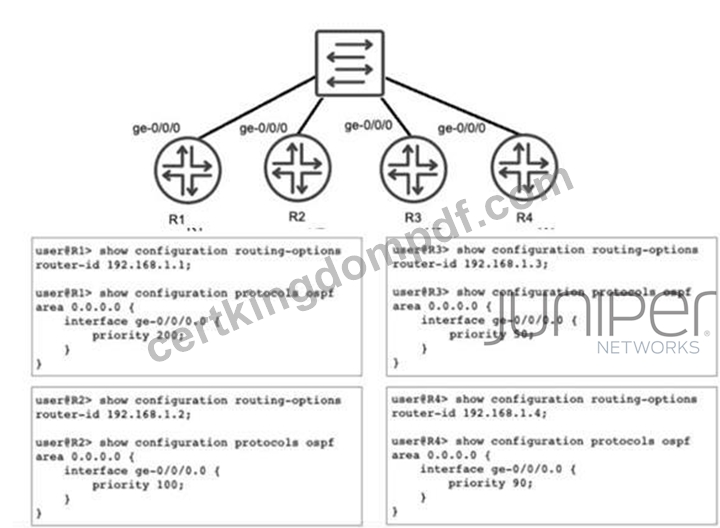
Referring to the exhibit, you have configured R1, R2, R3, and R4 to be a part of OSPF area 0 and you have connected them to a broadcast segment. Assuming all four routers come online within one minute of each other, which router becomes the DR and which router becomes the BDR?
- A. R1 is the DR and R4 is the BDR
- B. R4 is the DR and R1 is the BDR
- C. R1 is the DR and R2 is the BDR
- D. R4 is the DR and R3 is the BDR
Answer: C
Explanation:
In OSPF networks, when multiple routers are connected to a shared multi-access broadcast segment (like an Ethernet switch), they undergo an election process to select aDesignated Router (DR)and aBackup Designated Router (BDR). This mechanism is essential for reducing the number of adjacencies and limiting the volume of Link State Advertisement (LSA) flooding on the segment.
The OSPF election process follows a strict hierarchy based on the following criteria:
* Interface Priority:The router with the highest OSPF interface priority is elected as the DR. The router with the second-highest priority becomes the BDR. In Junos, the default priority is 128, but it can be manually configured between 0 and 255.
* Router ID:If there is a tie in priority, the router with the numerically highest Router ID (RID) wins the election.
Analyzing the configuration provided in the exhibit:
* R1:Priority 200, Router-ID 192.168.1.1
* R2:Priority 100, Router-ID 192.168.1.2
* R3:Priority 50, Router-ID 192.168.1.3
* R4:Priority 90, Router-ID 192.168.1.4
Comparing the priority values,R1 has the highest priority (200)and therefore becomes theDR. The next highest priority value among the remaining routers is100, which belongs to R2, making it theBDR. Although R4 has a higher Router ID than R2, the priority value is evaluated first and takes precedence.
Since all routers came online within a short window (one minute), they participate in the same election cycle, ensuring the configured priorities dictate the outcome rather than "first-come, first-served" preemption behavior common in OSPF once a DR is already established.
NEW QUESTION # 39
You are designing an MPLS network and want to ensure that traffic traverses an LSP between PE routers that follow an explicit path through the core. Which protocol would accomplish this task?
- A. LDP
- B. RSVP
- C. BGP
- D. IS-IS
Answer: B
Explanation:
In a Juniper Networks MPLS environment, the selection of a signaling protocol depends heavily on the requirement for traffic engineering and path control. To satisfy the requirement for anexplicit path-where the network architect defines specific hop-by-hop routers that the traffic must traverse-theResource Reservation Protocol (RSVP)is the necessary choice.
According to Juniper documentation, RSVP (specifically RSVP-TE) supports the use ofExplicit Route Objects (EROs). When you configure an LSP in Junos OS, you can define a path consisting of a series of IP addresses (strict or loose hops). RSVP then signals the LSP along that exact sequence of routers, reserving resources and establishing labels as it goes. This allows for precise control over the network's traffic patterns, enabling administrators to steer traffic away from congested links or toward specific high-bandwidth paths.
In contrast,LDP (Label Distribution Protocol)(Option D) is a "best-effort" signaling protocol. LDP strictly follows the Interior Gateway Protocol (IGP) shortest path. It does not support explicit paths or traffic engineering constraints; it simply builds a "mesh" of labels based on the existing routing table.IS-IS(Option C) is an IGP used to populate the routing table and TED but does not signal labels.BGP(Option A) is used for service delivery (like L3VPNs) but relies on an underlying transport LSP (built by RSVP or LDP) to reach its next hop. Therefore, only RSVP provides the mechanism for explicit path manipulation.
NEW QUESTION # 40
Which IS-IS adjacency state indicates that hello packets have been exchanged but the adjacency is not yet fully established?
- A. loading
- B. initializing
- C. up
- D. two-way
Answer: B
Explanation:
In theIS-IS (Intermediate System to Intermediate System)protocol, the process of forming an adjacency between two neighbors follows a specific sequence of states. While OSPF uses states like "Init," "Two-Way," and "Full," IS-IS uses a slightly different nomenclature within its state machine.
According to Juniper Networks technical documentation, when a router first sends anIS-IS Hello (IIH) PDU and receives one back from a neighbor, but has not yet confirmed that the neighbor "sees" it back, the adjacency enters theInitializingstate. Specifically, on a point-to-point link, the state transitions fromDownto Initializingas soon as the first PDU is received. On a broadcast network (like Ethernet), the Initializing state indicates that the local router has received a Hello PDU from the neighbor, but the local router's own System ID is not yet listed in the neighbor's list of "seen" neighbors (the neighbor's Hello PDU does not yet contain the local router's MAC address).
The adjacency only moves to theUpstate (Option C) once bi-directional communication is confirmed- meaning both routers have seen each other's System IDs in the incoming Hello PDUs.
Why other options are incorrect:
* Loading (Option A):This is an OSPF state, not an IS-IS state. In IS-IS, database synchronization happens after the adjacency is Up.
* Two-Way (Option D):While functionally similar to the state IS-IS is achieving, "Two-Way" is the specific terminology for OSPF. In IS-IS, the intermediate step between knowing a neighbor exists and having a fully functional adjacency is strictly calledInitializing.
NEW QUESTION # 41
Exhibit: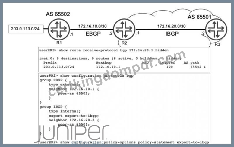
Referring to the exhibit, R1 is advertising prefix 203.0.113.0/24 to R2 over EBGP. R2 is configured to advertise this prefix into IBGP. R3 receives the 203.0.113.0/24 route, however the route is hidden.
Which configuration statement do you need to add to R2 to solve this problem?
- A. set policy-options policy-statement export-to-ibgp then next-hop self
- B. set protocols bgp group EBGP export export-to-ibgp
- C. set policy-options policy-statement export-to-ibgp from route-filter 203.0.113.0/24 orlonger
- D. set policy-options policy-statement export-to-ibgp then local-preference 50
Answer: A
Explanation:
In Juniper Networks Junos OS, a "hidden" route in the BGP table typically signifies that the router has received the prefix but cannot install it into the active routing table because theBGP next hop is unreachable
. This is a common occurrence in service provider environments when transitioning betweenExternal BGP (EBGP)andInternal BGP (IBGP).
According to Juniper technical documentation, when an EBGP speaker (R1) advertises a prefix to its peer (R2), it sets the next hop to its own interface IP address ($172.16.10.1$). By default, when R2 re-advertises that prefix to its IBGP peer (R3), itpreserves the original EBGP next-hop address. Unless R3 has a specific route in its Interior Gateway Protocol (IGP) or a static route to reach the $172.16.10.1$ subnet, it will mark the route as unusable (hidden).
In the exhibit, the show route output onR3explicitly shows the nexthop for $203.0.113.0/24$ as
$172.16.10.1$. Since this route is marked "hidden," we can conclude R3 does not know how to reach R2's external peering link. To resolve this, the network administrator must modify the next-hop attribute before the route is sent to R3.
By adding the statementset policy-options policy-statement export-to-ibgp then next-hop self(Option B) on routerR2, R2 will replace the external next-hop ($172.16.10.1$) with its own internal peering address ($172.16.20.1$) before advertising the route to R3. Because R3 already has a direct or IGP connection to R2's internal address, it will successfully resolve the next hop, and the route will transition from "hidden" to
"active."
Option A is unnecessary because the route is already being exported; Option C is redundant as the policy is already applied to the IBGP group; and Option D changes path preference but does not solve the underlying reachability problem.
NEW QUESTION # 42
Which feature allows Junos OS to perform recursive lookups for static route next hops?
- A. reject
- B. resolve
- C. next-table
- D. discard
Answer: B
Explanation:
In standard routing, astatic routeis typically considered valid only if the specified next-hop IP address is directly reachable on a local subnet. However, in complex service provider designs, the next-hop might be a
"distant" IP address that is reachable through another route (such as a BGP route or another static route). This process of looking up a next-hop within another routing entry is calledrecursive lookup.
In Junos OS, theresolve (Option A)parameter is explicitly used to enable this behavior for static routes.
According to Juniper technical documentation, when you append the resolve keyword to a static route configuration, you are instructing the Routing Engine to search the routing table to find a path to that distant next-hop.
For example:
set routing-options static route 10.1.1.0/24 next-hop 192.168.100.1 resolve If 192.168.100.1 is not on a local interface but is reachable via an OSPF route, the router will "resolve" the path and install the 10.1.1.0/24 route into the forwarding table using the OSPF path's exit interface.
Why other options are incorrect:
* Discard (Option B)andReject (Option C)are "next-hop types" used to drop traffic, either silently (discard) or by sending an ICMP unreachable message (reject).
* Next-table (Option D)is used forInter-VRF routing, where the router is told to look up the destination in a completely different routing instance (like a VRF table), which is a different architectural function than a recursive next-hop lookup within the same table.
NEW QUESTION # 43
Exhibit:
user@R2> show route 198.51.100.1
inet.0: 19 destinations, 19 routes (19 active, 0 holddown, 0 hidden)
Restart Complete
+ = Active Route, - = Last Active, * = Both
198.51.100.1/32 *[Static/5] 5d 21:02:26
> to 203.0.113.65 via ge-0/0/3.0
user@R2> show route 172.20.110.0/24
inet.0: 19 destinations, 19 routes (19 active, 0 holddown, 0 hidden)
Restart Complete
+ = Active Route, - = Last Active,
* = Both
172.20.110.0/24 *[Static/5] 10:43:01
> via gr-0/0/0.0
Referring to the exhibit, traffic destined to which network will be sent through the tunnel?
- A. 203.0.113.65
- B. 0.0.0.0/0
- C. 198.51.100.1/32
- D. 172.20.110.0/24
Answer: D
Explanation:
To determine which traffic is being sent through a tunnel in a Junos OS environment, an administrator must analyze the routing table output for the exit interface associated with each destination prefix. The provided exhibit shows the results of the show route command on routerR2for two specific destination networks.
In the first output, the destination198.51.100.1/32is an active static route. The next-hop information specifies that traffic for this address is sent to the gateway 203.0.113.65 via the interfacege-0/0/3.0. According to Juniper Networks interface naming conventions, the prefixge-denotes aGigabit Ethernetinterface, which represents a standard physical connection. Therefore, this traffic does not traverse a tunnel.
In the second output, the destination172.20.110.0/24is also an active static route. However, the next-hop for this network is listed asvia gr-0/0/0.0. In the Junos operating system, thegr-prefix explicitly identifies a Generic Routing Encapsulation (GRE) tunnel interface. GRE is a widely used protocol in service provider networks to encapsulate various network layer protocols over an IP backbone, effectively creating a virtual point-to-point link. Because the routing table has installed the route for 172.20.110.0/24 specifically via the gr- interface, all traffic destined for this network will be encapsulated and sent through the tunnel.
The other choices are incorrect for the following reasons:
* 203.0.113.65 (Option B):This is the next-hop IP address for the physical Gigabit Ethernet path; it is not a destination network directed to a tunnel.
* 0.0.0.0/0 (Option C):There is no information in the exhibit regarding a default route.
* 198.51.100.1/32 (Option D):As identified by thege-interface prefix in the exhibit, traffic for this destination is sent via a physical Ethernet link.
NEW QUESTION # 44
Exhibit: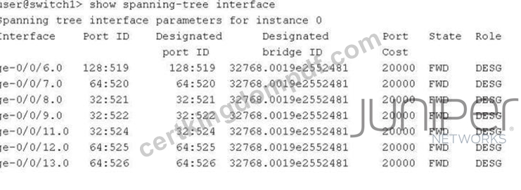
Referring to the exhibit, which two statements are correct? (Choose two.)
- A. The bridge priority for switch1 is 32k.
- B. The switch1 device is using VSTP.
- C. The ge-0/0/8, ge-0/0/9, and ge-0/0/11 interfaces are using the default interface priority.
- D. The switch1 device is the root bridge.
Answer: A,D
Explanation:
In the provided exhibit, the output of the command show spanning-tree interface for switch1 reveals critical details about the Spanning Tree Protocol (STP) operational state.
The first correct statement is thatthe switch1 device is the root bridge(Option B). This is determined by comparing the "Port ID" column with the "Designated port ID" column, as well as checking the "Designated bridge ID". In the exhibit, for every interface listed (from ge-0/0/6.0 to ge-0/0/13.0), the Port ID and the Designated port ID are identical. Furthermore, every port is in the "FWD" (Forwarding) state with the
"DESG" (Designated) role. In a Spanning Tree topology, the root bridge is the only device where all active participating interfaces serve as designated ports, as it has no need for a "Root" port role (which points toward a root bridge).
The second correct statement is thatthe bridge priority for switch1 is 32k(Option D). Looking at the
"Designated bridge ID" column, we see the value 32768.0019e2552481. In Junos and general networking standards, the Bridge ID is composed of a bridge priority and the device's MAC address. The default priority for most Spanning Tree variants (STP, RSTP, MSTP) is 32,768, which is commonly referred to in shorthand as "32k".
Regarding the incorrect options:
* Option A:There is no evidence of VSTP (VLAN Spanning Tree Protocol); the output shows "instance
0," which is typical for IEEE standard RSTP or STP.
* Option C:The Port IDs for ge-0/0/8, ge-0/0/9, and ge-0/0/11 all start with "32" (e.g., 32:521), whereas the default port priority is typically 128 (as seen in ge-0/0/6.0 with 128:519). This indicates that the interface priorities for these specific ports have been manually tuned to a non-default value.
NEW QUESTION # 45
By default, which routing table contains a list of all ingress LSPs?
- A. inet.3
- B. inet.2
- C. inet.0
- D. inet.1
Answer: A
Explanation:
In the Juniper Networks Junos operating system, the management of routing information is partitioned into several distinct routing tables (RIBs), each serving a specific architectural purpose. When dealing with Multiprotocol Label Switching (MPLS), understanding the distinction between inet.0 and inet.3 is fundamental for troubleshooting and traffic engineering.
Theinet.3routing table is specifically designed to store the egress IPv4 addresses ofLabel-Switched Paths (LSPs). When an ingress router successfully establishes an LSP (via RSVP or LDP), it places the host address of the egress router (the tail-end) into the inet.3 table. This table is not used for general packet forwarding; instead, it is primarily used by theBorder Gateway Protocol (BGP)for next-hop resolution. When BGP receives a route, it checks both inet.0 and inet.3 to resolve the next hop. If a matching entry exists in inet.3, the router knows it can reach that destination via an MPLS tunnel, allowing for the encapsulation of BGP traffic within MPLS.
In contrast,inet.0is the default unicast routing table used for standard IPv4 forwarding and contains routes learned via IGPs (OSPF, IS-IS) or static routing.inet.1is utilized for multicast forwarding (MBGP), andinet.2 is typically used for Multicast Source Discovery Protocol (MSDP) or RPF checks in multicast environments.
By isolating LSP egress points in inet.3, Junos prevents MPLS-specific paths from interfering with standard IGP path selection unless the administrator explicitly chooses to merge them (e.g., using the traffic- engineering bgp-igp command). Therefore, by default, the ingress router maintains its list of reachable LSP endpoints in inet.3.
NEW QUESTION # 46
Which IPv6 extension header is used to specify intermediate nodes for a packet's path?
- A. fragment
- B. destination options
- C. hop-by-hop options
- D. routing
Answer: D
Explanation:
In the IPv6 architecture, the base header is kept at a fixed size of 40 bytes to streamline processing. Any additional features or options are handled byExtension Headers, which are inserted between the IPv6 header and the upper-layer protocol. According to Juniper Networks technical documentation and RFC 8200, when a source node needs to list one or more intermediate nodes to be "visited" on the way to the final destination, it utilizes theRouting extension header (Option B).
The Routing header is functionally similar to the "Source Route" option in IPv4. When a packet contains a Routing header, it is addressed to the first intermediate node listed in the header. That node examines the header, swaps its own address with the next address in the list, and forwards the packet. This process continues until the packet reaches the final destination. This is a foundational component for technologies like Segment Routing over IPv6 (SRv6), where the Routing header (specifically the Segment Routing Header or SRH) is used to steer traffic through a specific set of service instructions or nodes.
To distinguish this from the other options:
* Hop-by-hop options (Option A):These carry information that must be examined byeverynode along the path (such as Router Alert), not just specific intermediate nodes.
* Fragment (Option C):This is used only when the source node needs to fragment a packet that exceeds the path MTU.
* Destination options (Option D):These carry optional information intended specifically for the destination node (or nodes listed in a Routing header), but they do not dictate the path themselves.
NEW QUESTION # 47 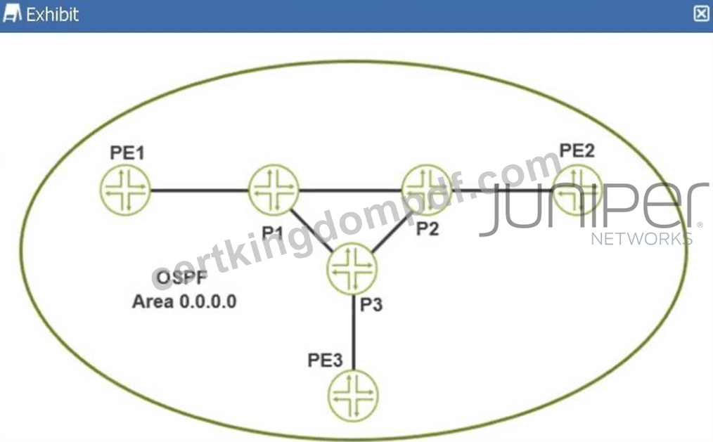
Referring to the exhibit, which protocol would automatically create a full mesh of label-switched paths between MPLS-enabled routers?
- A. BGP
- B. RSVP
- C. BFD
- D. LDP
Answer: D
Explanation:
In Juniper Networks Junos OS, theLabel Distribution Protocol (LDP)is specifically designed to automate the creation of Label Switched Paths (LSPs) based on the information provided by the underlying Interior Gateway Protocol (IGP), such as OSPF or IS-IS. When LDP is enabled on a set of interfaces within an OSPF area (as shown in the exhibit with Area 0.0.0.0), it automatically discovers neighbors and exchanges label mappings for all known unicast routes in the routing table.
The defining characteristic of LDP in this context is its "topology-driven" nature. Unlike RSVP (Resource Reservation Protocol), which typically requires the manual configuration of each LSP ingress point and destination, LDP follows the IGP's shortest path tree to automatically build afull meshof LSPs between all participating routers. This means that every Provider Edge (PE) and Provider (P) router in the exhibit-PE1, PE2, PE3, P1, P2, and P3-will establish label-switched connectivity to every other router without the administrator having to define individual tunnels.
LDP accomplishes this through a downstream-unsolicited label distribution mode by default in Junos. Each router assigns a local label for its loopback address and other prefixes and advertises these to its neighbors.
Because every router is performing this action for every reachable prefix in the OSPF domain, a complete fabric of label-switched paths is formed. While RSVP is more robust for traffic engineering and bandwidth reservation, LDP is the preferred protocol for creating a simple, scalable full mesh of LSPs for applications like Layer 3 VPNs or internal BGP tunneling where complex path manipulation is not required. BFD is a failure detection protocol, and BGP is used for service signaling, making LDP the only correct choice for automatic mesh creation.
NEW QUESTION # 48
Which two statements regarding GRE and IP-IP tunnels are correct? (Choose two.)
- A. These tunnels do not offer encryption mechanisms.
- B. These tunnels do not add any overhead to the packets that traverse them.
- C. These tunnels offer secure encryption mechanisms.
- D. These tunnels add additional overhead to the packets that traverse them.
Answer: A,D
Explanation:
In Juniper Networks Junos OS,Generic Routing Encapsulation (GRE)andIP-in-IP (IP-IP)are common tunneling mechanisms used to transport packets across a network by encapsulating them within another protocol. Understanding the header structure and the limitations of these protocols is essential for proper MTU (Maximum Transmission Unit) management and security design.
Overhead (Option A):
Both GRE and IP-IP tunnels operate by adding an additional IP header to the original packet. An IP-IP tunnel (Protocol 4) adds a20-byteIPv4 header. A GRE tunnel (Protocol 47) adds the same20-bytedelivery IP header plus a minimum4-byteGRE header (totaling 24 bytes, which can increase if keys or sequencing are used).
Because these headers are added to the payload, the total size of the packet increases. This "overhead" means that if the original packet was already at the MTU limit (e.g., 1500 bytes), the encapsulated packet will exceed it, potentially leading to fragmentation or the need to adjust theTCP MSS (Maximum Segment Size).
Encryption (Option D):
Crucially, according to Juniper Service Provider documentation, neither GRE nor IP-IP provides native encryptionor data confidentiality. They are encapsulation protocols, not security protocols. The payload remains in cleartext and is visible to any device along the path. If security and encryption are required for data traversing these tunnels, they must be combined withIPsec (IP Security). While GRE is often used as the
"carrier" for IPsec (to allow multicast or dynamic routing protocols which IPsec alone does not support), the GRE protocol itself remains an unencrypted delivery mechanism. Therefore, statements A and D accurately describe the architectural behavior of these tunnel types.
NEW QUESTION # 49
You are asked to configure interfaces on Juniper devices to support dual VLAN tags. In this scenario, which two interface statements would accomplish this task? (Choose two.)
- A. flexible-vlan-tagging
- B. stacked-vlan-tagging
- C. gigether-options
- D. vlan-tagging
Answer: A,B
Explanation:
To supportdual VLAN tagging(often referred to as Q-in-Q or 802.1ad), a Juniper interface must be configured to process more than one 802.1Q header. In Junos OS, this is handled at the physical interface level ([edit interfaces <interface-name>]).
According to Juniper Service Provider documents, two primary configuration statements enable this capability:
* stacked-vlan-tagging (Option D):This is the traditional command used to enable an interface to accept frames with two VLAN tags. When this is enabled, the router expects an outer "service" tag and an inner "customer" tag. This is specifically used in provider edge scenarios where a service provider is tunneling multiple customer VLANs.
* flexible-vlan-tagging (Option A):This is a more modern and versatile command. It allows the interface to support a mix of different encapsulation types across different logical units. For example, with flexible-vlan-tagging, you can have one logical unit (unit 10) doing standard single-tagging and another logical unit (unit 20) doing dual-tagging (vlan-tags outer X inner Y). This is the preferred method on newer hardware (like the MX Series) because it provides the highest level of configuration flexibility.
Vlan-tagging (Option C)only enables the interface to support a single 802.1Q tag, andgigether-options (Option B)contains physical-layer settings like auto-negotiation or flow control, which do not influence VLAN encapsulation. Therefore, A and D are the correct mechanisms for enabling dual-tag support.
NEW QUESTION # 50
Which OSPF packet type is used to initiate and maintain neighbor relationships?
- A. Hello
- B. Link-State Acknowledgment
- C. Link-State Update
- D. Database Description
Answer: A
Explanation:
TheHello packetis the most basic, yet most vital, component of the OSPF protocol. It serves as the primary mechanism for neighbor discovery, parameter negotiation, and "keepalive" functionality. Per Juniper Networks' routing documentation, OSPF routers use the Hello protocol to dynamically discover other OSPF- enabled routers on their directly connected segments.
When OSPF is enabled on a Junos interface, the router begins multicasting Hello packets (typically to the
224.0.0.5"All OSPF Routers" address). This initiates the neighbor relationship. For two routers to move beyond theInitstate and become neighbors, they must agree on several critical parameters contained within the Hello packet:
* Area ID:Routers must be in the same OSPF area.
* Authentication:Passwords or keys must match.
* Timers:The Hello and Dead intervals must be identical.
* Options:Such as Stub area flags.
Beyond the initial "initiation," the Hello packet is used tomaintainthe relationship. By continuously sending these packets at a fixed interval (the Hello interval), a router signals to its peers that it is still functional. If a router stops receiving Hello packets from a neighbor for a duration exceeding theDead Interval, it declares the neighbor "down," flushes the associated LSAs from the database, and triggers a new SPF calculation.
Furthermore, on multi-access networks like Ethernet, the Hello packet is the vehicle for the election of the Designated Router (DR)andBackup Designated Router (BDR). By exchanging priority values and Router IDs within the Hello packets, the segment can elect a central point of contact to minimize the number of adjacencies required on the wire.
NEW QUESTION # 51
You have configured an MPLS LSP that begins on R1 and terminates on R5 using the Junos default settings.
Referring to the exhibit, which router will perform only label swap operations?
- A. R4
- B. R3
- C. R5
- D. R1
Answer: B
Explanation:
In an MPLS network, routers are categorized by their role along a Label Switched Path (LSP). In this scenario, the LSP originates onR1 (Ingress LER)and terminates onR5 (Egress LER). Between these two endpoints are the Provider (P) routers, also known as Transit Label Switching Routers (LSRs), which include R2, R3, and R4.
To identify which router performsonlylabel swap operations, we must look at the standard Junos data plane behavior:
* R1 (Ingress LER):Performs aPushoperation. It receives native IP traffic from Networks 1 or 2, looks up the destination, and imposes (pushes) an MPLS label onto the packet before sending it to R2.
* R2 and R3 (Transit LSRs):These routers perform aSwapoperation. They receive a labeled packet, look up the incoming label in their Label Forwarding Information Base (LFIB), replace it with an outgoing label provided by the downstream neighbor, and forward it.
* R4 (Penultimate Hop):By default, Junos usesPenultimate Hop Popping (PHP). Because R4 is the second-to-last router before the egress (R5), the egress router R5 advertises an "implicit-null" label (Label 3) to R4. This instructs R4 to perform aPopoperation-removing the MPLS label entirely-and sending the native IP packet to R5.
* R5 (Egress LER):Receives the packet (which is already unlabeled due to PHP) and performs a standard IP route lookup to reach the final destination in Network 3 or 4.
Among the options provided,R3is the only router that is a transit LSR butnotthe penultimate hop. While R2 also performs a swap, it is not an option. R4 performs a Pop (due to PHP), R1 performs a Push, and R5 performs an IP lookup. Therefore, R3 is the correct answer as it solely performs the label swap operation.
NEW QUESTION # 52
Exhibit: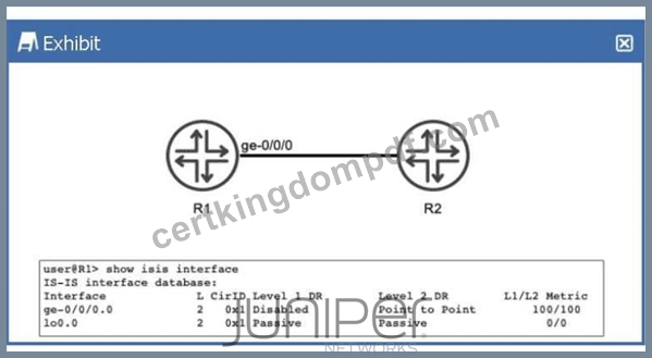
Referring to the exhibit, R1 and R2 are configured to run IS-IS. The IS-IS adjacency between R1 and R2 is up. What does the output of the show isis interface command tell you about R1?
- A. R1 only forms a Level 2 adjacency with R2.
- B. R1 is not configured to use wide metrics.
- C. R1 sends Level 1 hello PDUs to R2.
- D. R1 advertises a Level 1 metric of 100 and a Level 2 metric of 100 toward R2 in its link-state PDU.
Answer: A
Explanation:
In theIS-IS (Intermediate System to Intermediate System)protocol as implemented in Junos OS, routers can operate at two hierarchical levels:Level 1 (L1)for intra-area routing andLevel 2 (L2)for inter-area backbone routing. By default, a Juniper router and its interfaces are configured to act asLevel 1/2, meaning they will attempt to form adjacencies at both levels simultaneously.
According to Juniper Networks technical documentation, the show isis interface command provides a granular view of how the protocol is interacting with specific local links. In the provided exhibit, we must examine the L (Level)column and theDR (Designated Router)status columns to understand R1's operational state.
* Level Configuration:Under the L column for both the physical interface ge-0/0/0.0 and the loopback lo0.0, the value is strictly2. This indicates that these interfaces have been explicitly configured to operate only at Level 2.
* Adjacency Capabilities:For the interface ge-0/0/0.0, the Level 1 DR field is marked asDisabled. This confirms that R1 is not participating in Level 1 operations on this link; it will not transmit Level 1 Hello PDUs, nor will it listen for them. Consequently, R1 is incapable of forming a Level 1 adjacency with R2 on this segment.
* Metric Implications:The exhibit shows an L1/L2 Metric of100/100. In Junos, "narrow" metrics (the default) are limited to a maximum value of 63 per interface. A metric of 100 indicates thatwide metrics (wide-metrics-only) have been enabled. Therefore, option A is incorrect because the routerisusing wide metrics.
Since the prompt states the adjacency is "up," and the interface is restricted to Level 2, we can conclude that R1 only forms a Level 2 adjacency with R2 (Option B). Even though an L1 metric of 100 is displayed in the table as a configured value, it is not actually "advertised" in a Link-State PDU because the Level 1 protocol is disabled on that interface.
NEW QUESTION # 53 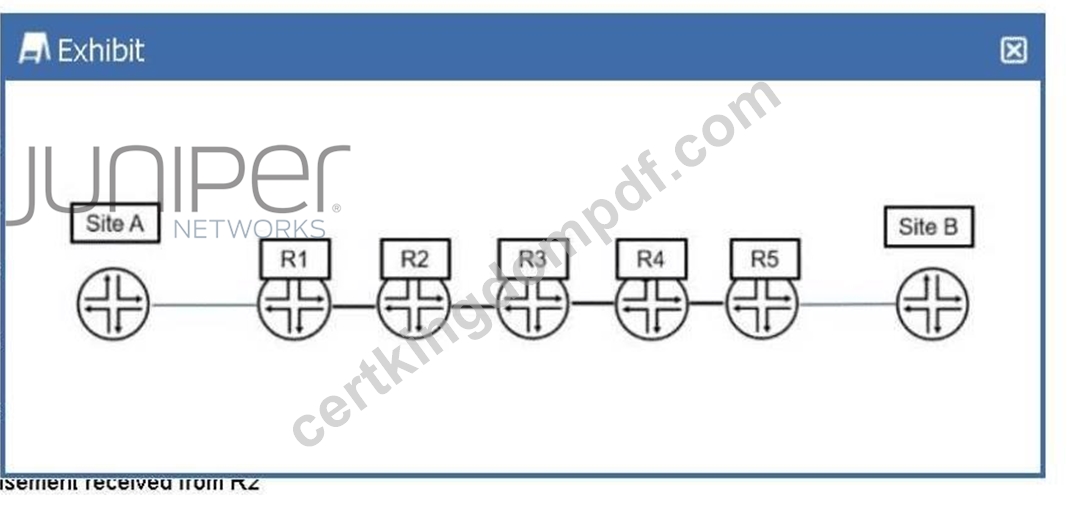
In the exhibit, Site A is sending traffic to Site B. R1 adds MPLS label 7166 to direct the traffic to R5. Which two criteria did R1 use to determine which label number to add to the traffic? (Choose two.)
- A. the source address of the traffic
- B. a label number advertisement received from R2
- C. a label number received from R5
- D. the destination address of the traffic
Answer: B,D
Explanation:
In a Juniper Networks MPLS environment, the process by which a router determines how to forward traffic involves both the control plane and the data plane. When R1 (acting as an Ingress Label Edge Router, or LER) receives an IP packet from Site A destined for Site B, it must perform a lookup to decide whether to forward the packet via standard IP routing or via an MPLS Label Switched Path (LSP).
The first criterion R1 uses is thedestination address of the traffic(Option C). Upon receiving the native IP packet, R1 looks up the destination IP in its routing table (typically inet.0). If the destination matches a prefix that is associated with an LSP-such as the loopback address of R5 or a prefix reachable via R5-the router identifies the appropriate Forwarding Equivalence Class (FEC). The FEC essentially groups packets that should be forwarded in the same manner over the same path. Without identifying the destination, the router cannot map the traffic to the correct MPLS tunnel.
The second criterion is thelabel number advertisement received from R2(Option D). MPLS relies on downstream label allocation. In this topology, R2 is the immediate downstream "next hop" for R1 on the path to Site B. For the LSP to be established, R2 must signal a label to R1 using a protocol like LDP (Label Distribution Protocol) or RSVP (Resource Reservation Protocol). This label (in this case, 7166) tells R1: "If you want to send traffic to the destination associated with this LSP, wrap it in this specific label so I know how to process it." R1 does not use the source address (Option A) for standard label mapping, nor does it receive the label directly from R5 (Option B) in a hop-by-hop signaling model; it must use the label provided by its direct neighbor, R2. Therefore, by combining the destination IP (to find the path) and the label provided by the next hop (to encapsulate the packet), R1 successfully directs the traffic through the MPLS core.
NEW QUESTION # 54
During OSPF neighbor establishment, which packet type is used to describe the contents of the link-state database?
- A. Link-State PDU (LSP)
- B. Hello packet
- C. Link-State Request (LSR)
- D. Database Description (DBD)
Answer: D
Explanation:
In theOSPF (Open Shortest Path First)protocol, ensuring that all routers within an area have a synchronized Link-State Database (LSDB)is fundamental to building a consistent loop-free topology. During the adjacency formation process-specifically when transitioning from theExStartstate to theExchangestate- routers must determine what information they are missing from their neighbors without sending the entire database at once, which would be highly inefficient.
TheDatabase Description (DBD)packet, also known as a DDP, is the mechanism used for this summary exchange. According to Juniper Networks technical documentation, the DBD packet does not contain full Link-State Advertisements (LSAs). Instead, it contains only theLSA headers, which include the LSA type, the ID of the advertising router, and the sequence number.
By exchanging these headers, a Juniper router can compare the neighbor's database summary against its own local LSDB. If the router identifies a header in the DBD packet that represents a newer or missing entry, it records that LSA in its "Link-State Request List." This collaborative "handshake" ensures that only the necessary, updated information is requested in the subsequentLink-State Request (LSR)phase. It is important to distinguish this from theLink-State PDU (LSP)mentioned in Option D, which is actually the term used in the IS-IS protocol, not OSPF. In OSPF, the functional unit is the LSA, and the transport vehicle for the initial summary is the DBD packet. This methodical synchronization is what allows OSPF to scale effectively in large service provider environments.
NEW QUESTION # 55
In an OSPF network, what is a purpose of a designated router?
- A. to flood routes to all other OSPF devices in the entire domain
- B. to assign an OSPF router ID to all routers in the OSPF segment
- C. to forward traffic within the configured subnet
- D. to reduce OSPF traffic on the OSPF segment
Answer: D
Explanation:
On multi-access network segments, such asEthernet, OSPF could potentially face a scalability issue. If every router on a segment formed a full adjacency with every other router, the number of adjacencies would follow the formula $n(n-1)/2$. In a segment with 10 routers, this would result in 45 adjacencies, each generating redundant flooding of Link-State Advertisements (LSAs) and excessive Hello traffic.
To solve this, OSPF elects aDesignated Router (DR)and aBackup Designated Router (BDR). According to Juniper Networks documentation, the primary purpose of the DR is to act as a central point of contact for the segment, therebyreducing OSPF traffic (Option C).
Instead of every router syncing with every other router, they all form aFull adjacencyonly with the DR and BDR. When a router (a DR-Other) has an update, it sends it to the multicast address224.0.0.6(All DR Routers). The DR then acknowledges the update and floods it to all other routers on the segment using the multicast address224.0.0.5(All OSPF Routers). This "hub-and-spoke" signaling model within the local segment significantly minimizes the bandwidth consumed by protocol overhead and reduces the CPU load on the participating routers.
It is important to note that the DR's scope is limited to the local segment; it does not "assign IDs" (Option A) nor does it flood routes to the "entire domain" (Option D), as that is the responsibility of individual routers within their respective areas.
NEW QUESTION # 56
How are routing loops prevented in internal BGP networks?
- A. Internal BGP routes are never readvertised to other external BGP neighbors.
- B. External BGP routes are never readvertised to other internal BGP neighbors.
- C. External BGP routes are never readvertised to other external BGP neighbors.
- D. Internal BGP routes are never readvertised to other internal BGP neighbors.
Answer: D
Explanation:
The prevention of routing loops within an Autonomous System (AS) is handled differently than loop prevention between ASes. While External BGP (EBGP) uses the AS_PATH attribute to detect loops,Internal BGP (IBGP)does not modify the AS_PATH. Therefore, a different mechanism is required to ensure that a route does not circulate infinitely inside the network.
This mechanism is known as theIBGP Split Horizon rule. According to Juniper Networks documentation and the BGP standard (RFC 4271), a BGP speakermust not advertise a route learned via an IBGP peer to any other IBGP peer. In simpler terms, "what is learned internally, stays local." This rule ensures that a route only travels one "hop" inside the AS-from the router that learned it from an external source to all other internal routers.
Because of this rule, IBGP routers do not naturally propagate routes through each other. This creates a requirement for afull meshof IBGP sessions, where every BGP-speaking router in the AS must have a direct peering session with every other BGP-speaking router. To mitigate the scaling issues of a full mesh in large service provider networks, architects useRoute ReflectorsorConfederations, which are authorized exceptions to the Split Horizon rule.
Option B is incorrect because EBGP peersdoadvertise EBGP routes to other EBGP peers (this is how the internet works). Option C is incorrect because EBGP-learned routesmustbe sent to IBGP peers so the internal network knows how to reach the outside world. Option D is incorrect because internal routesmustbe sent to external peers to advertise your network to the internet.
NEW QUESTION # 57
A BGP router receives two routes to the same prefix. One route has a higher local preference, while the other has a shorter AS path. In this scenario, which route would be selected?
- A. The route with the shorter AS path.
- B. The route with the lower origin code.
- C. The route with the higher local preference.
- D. The route with the lowest MED value.
Answer: C
Explanation:
TheBGP path selection algorithmis a deterministic process used by Juniper routers to select the single "best" path from the BGP table to be placed into the routing table (inet.0). This algorithm follows a specific, hierarchical set of rules. According to Juniper Networks technical documentation, the router evaluates attributes in a fixed order, and once a tie is broken at a specific step, the remaining steps are ignored.
The order of the primary BGP attributes in Junos OS is as follows:
* Highest Local Preference:This is the first attribute evaluated after the basic check for a reachable next hop. Local preference is used within an Autonomous System (AS) to prioritize one exit point over another.
* Shortest AS_PATH:If the local preference is equal, the router then evaluates the length of the AS_PATH attribute.
* Lowest Origin Code:(IGP < EGP < Incomplete).
* Lowest Multi-Exit Discriminator (MED).
In this specific scenario, the router compares a path with ahigher local preferenceagainst a path with a shorter AS path. Because theLocal Preferencecheck occurs at Step 1 and theAS_PATHcheck occurs later at Step 2, the router will select the path with the higher local preference immediately. The length of the AS path becomes irrelevant in this comparison because the tie was already broken by the local preference value.
This allows network administrators to override the default "shortest path" logic of BGP to prefer specific providers or links based on business requirements.
NEW QUESTION # 58
Exhibit: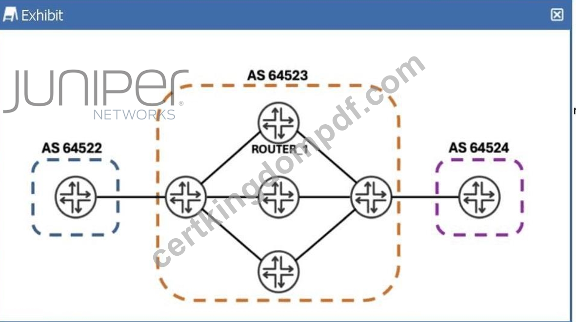
You must configure the router called ROUTER_1 to take all valid prefixes learned from internal BGP peers in AS 64523, and then re-advertise them to other internal BGP peers in the same autonomous system.
Referring to the exhibit, which configuration must you deploy on ROUTER_1 to accomplish this task?
- A. Configure ROUTER_1 to belong to a different autonomous system than the other BGP routers in your network.
- B. Configure a routing policy on ROUTER_1 that removes the no-export BGP community from all received prefixes.
- C. Configure ROUTER_1's internal BGP group with a routing policy that exports prefixes learned from internal BGP.
- D. Configure ROUTER_1's internal BGP group with the keyword cluster, followed by a unique 32-bit number.
Answer: D
Explanation:
In theBorder Gateway Protocol (BGP), theSplit Horizonrule is a fundamental loop-prevention mechanism for internal sessions. This rule dictates that a BGP speaker must not advertise a route learned from anInternal BGP (IBGP)peer to any other IBGP peer within the same Autonomous System (AS). This ensures that routes do not circulate infinitely inside a network, as IBGP does not modify the AS_PATH attribute. Consequently, to maintain full reachability, a network normally requires a "full mesh" of IBGP sessions, where every BGP- speaking router is directly peered with every other router.
In the provided exhibit,ROUTER_1is part of AS 64523. The requirement is for ROUTER_1 to take prefixes learned from its internal peers and re-advertise them to other internal peers in the same AS. This behavior is a direct violation of the standard Split Horizon rule. According to Juniper Networks technical documentation, the standard solution to scale IBGP without a full mesh is to configureRoute Reflection.
When a router is configured as aRoute Reflector (RR), it is permitted to "reflect" (re-advertise) routes learned from one IBGP peer to another. In Junos OS, the mechanism to enable Route Reflection is to configure acluster IDwithin the BGP group. By adding the cluster keyword followed by a unique 32-bit identifier (usually the router's loopback address) to the internal BGP group configuration, the router assumes the role of an RR. It then follows specific reflection rules:
* Routes learned from anEBGP peerare reflected to all IBGP peers.
* Routes learned from aRoute Reflector Clientare reflected to all other clients and non-clients.
* Routes learned from anon-clientare reflected to all clients.
Option A is incorrect because BGP advertisement rules are hard-coded; a standard export policy cannot override the Split Horizon rule. Option C handles traffic engineering tags but does not enable route reflection.
Option D would change the session to EBGP, which does not address the internal reachability requirement within AS 64523. Therefore, configuring the cluster ID is the only valid way to achieve the desired re- advertisement behavior.
NEW QUESTION # 59
Which two statements are correct about TLVs in IS-IS? (Choose two.)
- A. TLVs only support encoding IPv4 routing information.
- B. LSPs can only contain one TLV.
- C. TLVs allow flexible encoding of routing information.
- D. LSPs can contain multiple TLVs.
Answer: C,D
Explanation:
In the IS-IS protocol,TLVs (Type, Length, Value)are the fundamental building blocks used to carry information withinLink-State PDUs (LSPs). Unlike some other protocols that have a fixed, rigid packet format, IS-IS was designed from the ground up to be modular and extensible. This extensibility is achieved through the use of TLVs, which allow the protocol to carry different types of data without requiring changes to the core protocol state machine.
According to Juniper Networks technical documentation,TLVs allow flexible encoding of routing information (Option C). Each TLV specifies the "Type" of information it carries (such as neighbor information or IP reachability), the "Length" of that information, and the "Value" (the actual data). This architecture is what allowed IS-IS to easily support IPv6 by simply adding new TLVs (like TLV 236 for IPv6 reachability) without redesigning the protocol. It also supports Traffic Engineering (TE) extensions used in MPLS environments by adding TLVs that describe link bandwidth and administrative groups.
Furthermore, a singleLSP can contain multiple TLVs (Option D). When a Juniper router generates an LSP, it packs all the necessary information-such as the router's area addresses, its neighbors, and its local interface prefixes-into various TLVs and places them into a single PDU. If the amount of information exceeds the Maximum Transmission Unit (MTU) of the interface, the router will generate additional LSPs (fragmented LSPs) to carry the remaining TLVs.
Options A and B are incorrect because restricting an LSP to a single TLV would make the protocol incredibly inefficient, and the very nature of IS-IS is its ability to support multiple network layer protocols (not just IPv4) through its agnostic TLV-based transport.
NEW QUESTION # 60
......
Top Juniper JN0-364 Courses Online: https://www.certkingdompdf.com/JN0-364-latest-certkingdom-dumps.html
JN0-364 Practice Dumps - Verified By CertkingdomPDF Updated 67 Questions: https://drive.google.com/open?id=1adJuvWCqyrvUmzOiCIsg71IVDBsNp_Js